These stories usually start with what we're going to build.

A Calandra Racing Concepts Gen-X 10 R/T. This is a pan car. That is, most of the car is built off a sheet of flat material. At first, they were aluminum, later they transitioned to fiberglass, and then graphite (what we know now, as carbon fiber..) and amusingly, today, on carpet, back to aluminum.
I'll become clear what that pan is, as we build the car.
In the box you get everything you need, except most of the tools, tires, and a pinion. Given that these cars are usually raced with 17.5 or 21.5 motors, including the pinion would probably be a mistake anyway.

It's notable, that they give you a full tube of side damper tube grease, and a nice pen filled of shock oil. The only material they seemed less than generous about, was the diff grease, as that came in a vacuum seal tear off package, not unlike a ketchup packet.
The build of the car starts with the pan. It's in two parts, the aft section carrying the motor and rear axle, and the front half has everything else.

Pan cars, started as solid pans, then eventually grew cutouts. Those cutouts were there to control the rear pods movement. Cutouts evolved into the t-bar, where the cutout was replaceable. My F104w has a t-bar, and I have several bars for it to change the cars handling. (Though, technically they are H-shaped on the F104.)
And the ultimate iteration is this pivot ball design. Ultimate, in that the bar is completely free, and has no spring or force to it. Which depends on a whole lot of accessory parts to make work, but it provides the freest and least dependent on other factors rear suspension tuning. The CRC Gen-X10 has a pivot ball, and a main damper and spring, and side dampers, and side damper springs.
The pivot ball on the Gen-X10 is held down by the 2-56 pan head screws, and the whole mount is bolted down with the locknuts on either side. This provides some adjustment when you set the rear suspension up. The position of the pivot ball, in relation to the side links is critical, if the distances are off, you now have a triangulated mount for your rear axle, and that's exactly how you make it ~not~ move. The instructions tell you to feel for a "click" and that's the center mount going over center.

While we're there. Lets talk about good manuals. Tamiyas manuals are pretty. Tamiya's manuals will let you build the car. MST's manuals are on good material, and mostly well written. Both sets of manuals only have you build the car and do not teach you about your car. CRC's manual has little asides on many of the steps, telling you why you're doing something, and ensuring you have a quality build, and a good build experience.
For example, if you want to have a good time building a plastic R/C car, you're going to want a thread forming tap, and maybe some Vaseline. This lets you pre-tap all the holes so the car assembles quickly and straight. Perhaps you're building a touring car, and you want it tweak free. The Tamiya manual won't tell you to assemble it on a flat plate before tightening any top deck clamps.
CRC's manual, does all of this. First, they suggest building on a trusted flat surface. Second, they give examples of what tight, and free are. For the rear pod, they say to "feel for the click". And for the steering knuckles, they tell you, straight up, to over-tighten them, so you can work them free, then set them for the best fit. For the upper arms, they tell you about reaming the arms, but NOT the clamps.
As we go, i'll point out the steps where they tell you about tuning the car too.
We were talking about side links, weren't we?

There we go, side links. And no click either. For setting up the side links, it's important that they move freely. You tighten the 2-56 pan head screws, then back them off JUST a little, so the pivot is free. This gets into one of my few criticisms of the car. I think three of my pan head screws were not well formed, so they were hard to get the .050 wrench to properly grip. ... yes, I am a fastener snob.

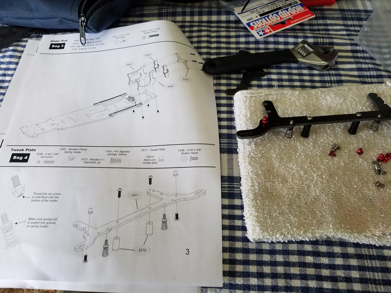
Time to build the pod. The pod design is good. With infinite ride height adjustment, and by using the same screws for the cross brace, they also got around needing more screws for that.

I keep taking photos of the manual, as it's just that good.

That's a better view of the cross brace. So, lets talk about the bridge you see there. That was built as a separate piece, then was bolted to the chassis.

The manual has you build this separate from the rest of the car. The black pillars are smooth plastic, and lack any way to hold them. Mine have some slight marks from the pliers I used to hold them from spinning.
The springs you see, are on molded seats, and those are attached to some setscrews. The manual shows you just how deep to put the setscrews. The manual also tells you a bit of what you do with those springs, rather than just assume you know how to tune it.
The outer ball joints, are for the side dampers.
Here's the bridge, installed.

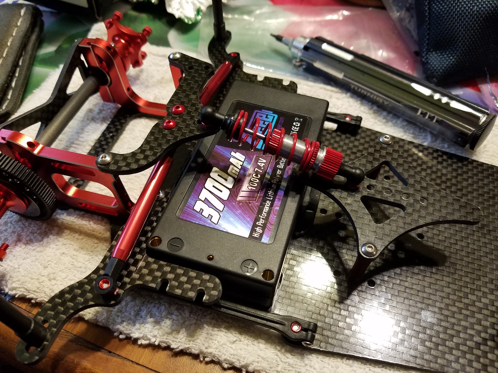
Next up is the rest of the superstructure. They support the side dampers, and the main shock.

The main shock brace on the center of the chassis has a whole lot of shock mounting points. The brace can be moved fore and aft 5mm too, as well as the shock mounting points on the top. The rear one uses aluminum screws for some reason, I can't figure out why... for the side damper mounts.
If you look closely, you can see a short body post, that's used for the receiver antenna, later.
So lets dress it up a bit. Shock, side dampers.

So, if you've never played with on road cars before, the side dampers are going to be a bit of a mystery to you. What they are is a plastic shaft, with a couple grooves in it. That sits inside of an aluminum tube. Before you assemble them, you coat the plastic shaft with thick lube. In this case, 20,000wt lube.

The center shock, is a small volume but very conventional shock. The piston needed some work to get it moving smoothly in the shock body. The only notable thing about the shock, is that it's got a long, long, nipple on the shock shaft guide. It's good.
That's when Easter dinner ended, and it was time to go home.

And now we build the front end.
That's a LOADED page there. It doesn't look like much. But just clearing that page was 40 minutes.

Other than that front bumper carbon, all of that is the front suspension.
The first parts they have you build, are the lower arms. They require press fitting the strut balls and then doing some fine tuning of the lock screw tension. They'll have you do this later with the upper struts.. but you should do this here, now, where you clamp them just a little tight, then wiggle the ball around till it starts to loosen up. Finally, relieve the tension on the clamps.

In the package, you get a lot of tuning bits. That includes reactive caster blocks, ride height blocks, and well get to a few of the other bits.

Here's the 5mm ride height blocks, which screw up into the reactive caster mounts. The manual recommended the 5deg blocks. The kit came with 0deg, and 10deg. In the background, you can see upper arm pivot shafts, and those darn 2-56 screws. One of those had a bad head on it.

The upper clamps may be excessive. Three bolts would likely be enough, but they look nice and symmetrical with 4. There's three clear-white washers on the upper arm. This alters static caster, and they're in the manual recommended place there. They should be freer than they are there. But I expect they'll wear in a bit.
Then you build the knuckles.

The knuckles have a very conventional bolted axle. The strut shaft is threaded, and is screwed into the knuckle. And then it's locked in place with a brass screw.

Here's the stack up installed in the lower arm. The washers provided are stepped, to provide a nice way of keeping the spring centered. It's an appreciated touch. I took this opportunity to do some more breaking in of the lower ball ball joint.
Getting pictures of the next two steps is really hard.

The manual handles it well. But what you do is screw the upper pivot ball into the upper arm through the knuckle. The upper ball allows adjustment for camber, and because the ball is so big, you get a nearly slop free interface to the upper strut mount.
Mentioned in the manual is the installation of the nut that holds the upper ball in place. The nut is plastic. Do the usual "turn backwards till it clicks" before screwing it into the knuckle. Then follow the directions for break-in.
Those arms mount to this thick, multi-layer stackup on the front of the chassis plate.

This stackup ends up leaving recesses for the servo mounting screws, and nets us adjustable front track. The screw holes are wonderfully tight. At least now, there is no slop, even without the bolts being tight.

The bolts that hold the arm assemblies on are ~big~. #10 wide pan head screws. And, since they're stressed bolts, they're black oxide normal steel screws. That's instead of the fancy SS you find many other places on the chassis, in less stresses locations.
Material choices are something that CRC seems to put some thought into.
Here we have the front bumper. That's hard, and is going to transfer all impact through the car. But if you look at the pile of fasteners back there, you'll see a lot of aluminum. That comes into play shortly.

Those aluminum spacers get topped with some stainless flat head bolts, and some washers.

That's one of the best bumper setups I've seen that didn't include massive molded mounts like you find from Tamiya.
So here's the most obvious example of "hey we are thinking about you" that CRC does for their customers.

That bumper, is held on, not only by aluminum screws, but by locknuts. Locknuts, to stop the maintenance pain. Aluminum so that bumper will sheer off before you break all sort of other parts of your car. I like seeing things like that. And along with the jokes, and tuning notes in the manual, I get the real impression that CRC cares for "us" who are buying their cars.

So next is the steering servo. The car came with aluminum servo mounts, which is nice! Probably more cost effective than having plastic mounts molded, but I definitely like the smattering of red. I.. didn't plan on the servo matching, but the 1/12 scale servo I had in stock matched nicely.

Then comes the rear axle. And... we hit my one stumbling block on this build. I was one bearing short. But the bearings are cheap... and I ordered another one. The rear axle is carbon, the spur is nice. The left hub is double clamping. the right hub is beautiful. The spacers are perfect. The threaded holes for the wheels and tires are proper running fit.
So that's it for the first build article. It was another week for the wheels, tires, and replacement bearing to show up. And I need to do the electronics setup.